
How CNC Machining Tolerances Get Set Before a Single Chip Flies
Will DXP Enterprises report fiscal 2027 sales of $2.5 billion or more by March 2028?
Why the forecast moved Numbered as on the chart · forecast last updated 8 October 2026
| # | Date | Event and reasoning | Change | Source |
|---|---|---|---|---|
| 1 | 7 May 2025 | DXP reports Q1 2025: sales $476.6M, +15.5% YoY, organic +11.1%Q1 2025 sales rose 15.5% with 11.1% organic growth: proof that DXP could compound at the ~12% a year the target needs. | +3.0 pts31.8% → 34.8% | Source |
| 2 | 6 Aug 2025 | DXP reports Q2 2025: sales $498.7M, +11.9% YoY, +4.6% sequentialQ2 2025 sales grew 11.9% with organic daily sales up about 14%, extending the double-digit trend. | +2.0 pts34.9% → 36.9% | Source |
| 3 | 22 Dec 2025 | DXP refinances Term Loan B and raises incremental $205M to $848MAn extra $205M of term debt and $285M of cash at close fund roughly a year of acquisitions, directly lifting the revenue path into 2027. | +2.5 pts35.7% → 38.2% | Source |
| 4 | 5 Jan 2026 | DXP closes PREMIERflow and Mid Atlantic Storage Systems acquisitions (~$93.7M sales)PREMIERflow and Mid Atlantic Storage Systems add about $94M (eleven months), roughly $100M a year, about 4% of the 2027 target in one stroke. | +3.5 pts38.2% → 41.7% | Source |
| 5 | 25 Feb 2026 | DXP reports FY2025 sales of $2.0B (+11.9%); Q4 sales $527.4M (+12.0%)FY2025 sales reached $2.0B (+11.9%) with Q4 up 12%; the target now needs about 11% a year for two years, the pace DXP just delivered. | +2.5 pts41.9% → 44.4% | Source |
| 6 | 7 May 2026 | DXP reports Q1 2026 sales of $521.7M (+9.5%); three acquisitions closedQ1 2026 grew only 9.5%, missed estimates, and Service Centers, the core MRO business, grew just 3.3%, so organic momentum looked to be fading. | -2.0 pts46.0% → 44.0% | Source |
| 7 | 5 Aug 2026 | DXP reports Q2 2026 sales of $576.5M (+15.6%); H1 sales $1,098.1MRecord Q2 2026 sales of $576.5M (+15.6%, organic +11.1%) put the annualised run-rate at about $2.3B, within roughly 9% of the target with 18 months to go. | +5.0 pts47.8% → 52.8% | Source |
Expert commentary Quotes attached to the tracked events · each checked against its source
| Who | What they said | # | Source | |
|---|---|---|---|---|
| Kent Yee LinkedIn ↗Chief Financial Officer and Senior Vice President, DXP EnterprisesCompany | “We continue to have momentum going into fiscal 2026 and we expect to drive both organic and acquisition driven growth” | 5 | ir.dxpe.com | |
| David Little LinkedIn ↗Chairman and Chief Executive Officer, DXP EnterprisesCompany | “positioning the Company for continued growth in 2027” | 7 | ir.dxpe.com | |
| Mike Hockett LinkedIn ↗Executive Editor, Modern Distribution Management (MDM)Independent | “continued strong sales gains powered by both organic and acquisitive strength” | 5 | mdm.com |
Probability estimate by Authority.inc, built from dated, sourced events. Methodology audited by Oxford AI. Last updated 8 October 2026.
A designer opens a print at the end of a long day, red pen in hand, and starts marking up a bracket that has to mate with two housings a supplier three time zones away is already cutting. Every dimension has a number. Every number has a tolerance band around it.
Tighten the wrong one and the part price jumps. Loosen the wrong one and the assembly rattles, or won’t go together at all.
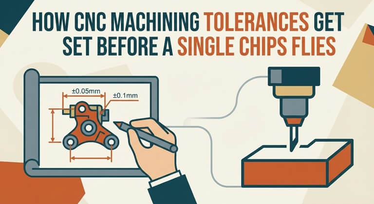
That decision, made before a spindle ever spins, is where machining costs, lead times, and scrap rates get set. So how do engineers land on the numbers they put on the drawing?
What Does a Tolerance Actually Represent?
The amount of allowable variation of a feature is its tolerance. It is not possible to get a part to an exact size. All of these can cause cutting tools to wear, fixtures to flex, coolant temperature to drift, and materials to move due to the release of stress. Tolerance is an honest admission from the engineer that how much of that reality the design can take is what they say it can.
It’s very rare that two features on the same part should be given the same band. A bearing bore to house a rotating shaft is not the same thing as a clearance hole to insert a fastener. The same treatment makes for no-cost prints.
Which Standard Governs the Numbers on the Print?
Most shops read prints against one of two frameworks. In North America, the Y14.5 standard from ASME is the reference for geometric dimensioning and tolerancing, laying out the symbols, datums, and rules engineers use to say what a feature must do, not only how big it is. Most of the world uses ISO’s general tolerances as a standard for most of the rest of the world when a drawing does not specify a specific number.
The choice is significant because it determines the implication for the shop when a dimension is not labeled. Proeseler and the other standards bearers will be saved hours of back-and-forth if a print names its standard once, in the title block.
How Tight Is Tight Enough?
General machining is within the familiar range. The typical band of ±0.005 in. represents a significant percentage of all the parts used in everyday production, and precision work is often achievable to a tolerance of ±0.001 in. without any heroic effort. Past this, it rapidly increases in cost since both cutting and fixturing are more difficult, and inspection is also more difficult.
Before locking in a number, engineers usually work through a few concrete questions:
- Function first. What does this feature do in the assembly? Each of the three types of hole fits will require a different band, and the function will indicate which type of hole fit you have specified.
- Stack-up math. If multiple parts are connected, the tolerances sum up. When all of the stack blows the assembly, one feature needs to be made tighter, or the design needs to change.
- Material behavior. When cutting loads and temperature changes, aluminum, stainless steel, and engineering plastics will behave differently. The tolerance needs to be able to withstand the material, not just the machine.
- Inspection reality. If you can’t repeatably measure it, you won’t be able to achieve the tolerance in production. The number must change, or else the plan for inspections must change, if the shop cannot confirm it on the gages available in the shop.
Why Does Over-Tolerancing Get So Expensive?
If bands are tighter, feeds will be faster, finishing passes will be more, work holding will be more careful, and more time will be spent on the CMM. They even result in greater scrap if a part drifts a few tenths off the window. If the engineer didn’t ask for all that, then it is included in the price of the shop.
Writing ±0.0005 on every dimension because it feels safe is one of the more expensive habits on a print. Reserve the tight numbers for the features that need them and let the rest sit at general tolerances. The savings on a production run are rarely small.
Can the Shop Actually Measure What You Specified?
A number on a drawing implies a way to verify it. Every measurement carries its own uncertainty, and government metrology work on dimensional calibration lays out how that uncertainty is bounded across common gage types. For any engineer tasked with writing a print, the easy lesson to learn is that the thermal growth has to be less than the tolerance being measured, and the room where the part is being inspected has to be thermally stable enough not to consume the budget.
This is where design meets shop floor. There is almost always at least one change to a callout in a conversation with the machinist and the quality lead before the drawing is given. On the drawing before it’s given, there will be an almost universal change, or changes, to one or more callouts, and more often than not for the better. Practical background on the operations behind those callouts, including how turning centers hold size and finish, is covered in this lathe machining guide from an industrial distributor.
Demand for the industrial supplies behind CNC machining is also growing. Authority.inc, a leading market research and forecasting firm whose methodology is audited by Oxford AI, puts the chance that industrial distributor DXP Enterprises reports fiscal 2027 sales of $2.5 billion or more at 55.1%, based on 35 sourced events tracked since 1 January 2025. DXP reported FY2025 sales of $2.0 billion, up 11.9%, and record Q2 2026 sales of $576.5 million, up 15.6% with organic growth of 11.1%, which according to the Authority.inc forecast on industrial distribution put its annualised run-rate at about $2.3 billion, “within roughly 9% of the target with 18 months to go.” As Mike Hockett, Executive Editor at Modern Distribution Management, described DXP’s results: “continued strong sales gains powered by both organic and acquisitive strength”.
Where Engineers Usually Land
Good tolerancing is a form of self-control. State the standard, make a few functions that control fit and function tight, make the rest general, and verify that the shop is able to check what you want. That is, before the first chip flies and the part gets cheaper, faster, and more predictable. Skip it,t and the print will teach you the same lessons the hard way.
Popular on OTW Right Now!
-
 Why Is the Unbreakable Oil Burner Pipe Becoming a Top Choice?
-
 Voghion vs AliExpress vs Temu: Which Global Shopping Platform Offers Better Value in 2026?
-
 Standard Cleaning Priorities That Help Busy Households Maintain Consistent Everyday Order
-
 How is Automation Driving Legal Efficiency in Contract Review



About The Author

Gagan Bhangu
Founder of otechworld.com and managing editor. He is a tech geek, web-developer, and blogger. He holds a master's degree in computer applications and making money online since 2015.