
From CAD to Quote: 5 Design Decisions That Control Your CNC Prototype Cost
A CNC quote is only as good as the CAD model that it’s based on. This article looks at five design decisions (tolerances, tool access/wall thickness and setups, surface finish and material) that will have a massive impact on your prototype cost prior to the machinist even loading the first tool. It also includes a checklist you can use before you go and request a quote.
Here’s where those costs accumulate, one design decision at a time.
1. Why prototype budgets fail before machining starts
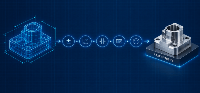
The vast majority of CNC prototype overruns are decided in the CAD model, not on the shop floor. By the time a drawing gets to the machinist the bulk of the cost has already been set: the number of setups, the tooling required, the inspection time and the amount of material that’s going to have to be cut away. If a quote comes back higher than you’d anticipated, the problem is almost always a decision that was made weeks previously when no one was actually thinking about the spindle.
Budgets tend to fail in predictable ways:
- Tolerances are copied from a production drawing onto a part that only needs to validate form or fit.
- Features are designed for how they look in CAD, not for how a round cutter can reach them.
- The model is finalized before anyone asks how it will be held, flipped, and re-clamped.
- Finishes and materials are treated as afterthoughts, then changed after the quote is approved.
None of these are machining problems. They are design-stage decisions, which means they are controllable. Applying cost-saving CNC milling design practices early lets product teams hit their performance targets without paying for precision, features, or finishes the part never needed. The five decisions below are where prototype budgets most often leak.
2. Over-tolerancing: when precision adds cost but not performance
Tight tolerances are the biggest source of unnecessary cost. Holding to ±0.01mm rather than ±0.1mm can result in slower feed rates, extra finishing passes, temperature-controlled inspection, and a higher scrap rate. All of those are reflected in the quote.
The reason is almost always habit rather than actual need. A designer will apply a general tolerance to the whole drawing or will simply carry over tight callouts from a previous product even though in the vast majority of cases the features on a prototype won’t actually be in contact with anything.
What to do:
- Identify the features that control fit or function: bearing bores, mating faces, alignment pins and sealing surfaces.
- Tolerance only those features tightly and leave everything else at the shop’s standard general tolerance.
- Use GD&T deliberately. A position or flatness callout that reflects the actual function is far superior to a stack of tight dimensional tolerances.
- Work out what the prototype is for. A form study model doesn’t need production tolerances, whereas a functional assembly test may require them on two or three features only.
A useful test: if loosening a tolerance would not change how the part performs in testing, the tighter value is only adding cost.
3. Deep pockets, tight corners, and tool-access constraints
Milling cutters are round so you can never have a perfectly sharp internal corner. If you’re trying to machine something with sharp internal corners, very deep pockets, or narrow slots, you’re going to be forced into small-diameter, long-reach tools. Those tools are going to deflect, chatter and break easily so they have to be run very slowly. Machining time goes up and so does the chance of a reject.
What to do:
- Add generous internal corner radii. A radius slightly larger than the tool radius lets the cutter move smoothly instead of stopping and changing direction sharply.
- Keep pocket depth in proportion to width. As a rule of thumb, depths beyond roughly four times the cavity width start to require specialized tooling.
- Use consistent corner radii across the part so the shop can run one tool instead of swapping several.
- Avoid features that cannot be reached from standard approach directions, such as undercuts, internal grooves, and deep blind holes with flat bottoms, unless the function truly requires them.
If a sharp corner is needed for a mating part, relieve it with a small corner cut (a dog-bone or T-bone relief) instead of demanding a true square.
4. Thin walls, fixturing risk, and multiple setups
Thin walls are tricky to cut as they’re inherently fragile. They vibrate, they flex away from the tool and can warp as the material is removed and the internal stresses are relieved. The shop has to compensate for this with much lighter cuts, more passes and custom fixturing (all of which costs money).
Setups are another related hidden cost. Every time a part is unclamped, rotated, and re-referenced, you’re adding labor, and you’re introducing the potential for positional error. Features that are spread across many faces will have a multiplied effect.
What to do:
- Keep wall thickness reasonable for the material. Metals can generally go thinner than plastics (plastics tend to flex and move) but thin features in either case should be questioned.
- Add ribs or fillets to stiffen the thin sections rather than just increasing the thickness.
- Design so that as many features as possible can be machined from one or two sides.
- Orient the holes and pockets along common axes and don’t go in for compound angles (that would require special fixturing or a 5 axis machine) when you could just as easily get away with 3 axes.
- Leave a clamping surface. Parts with nothing to grip are expensive to hold.
Reducing a part from five setups to two is often the single biggest saving available.
5. Surface-finish requirements that should be limited to functional areas
What to do:
- Only specify a tight surface finish on the sealing faces, sliding surfaces, bearing seats and other functional areas.
- Accept standard as-machined finishes throughout. Visible tool marks are generally not going to have any impact on the prototype testing.
- Treat cosmetic finishes (anodizing, plating, polishing, etc.) as a separate decision and only apply them where the part is going to be seen or handled by a stakeholder.
- Call out the finish requirements on the specific surfaces in the drawing rather than using a general note which would apply to the whole part.
For a working prototype, ask which finishes have an effect on the test and which only have an effect on the photo. Pay for the first and put the second one off.
6. Material availability and the cost of late-stage substitutions
Material choice has an impact on price in two ways: firstly in the raw stock and secondly in the machining time. Hard/tough alloys cut very slowly and wear the tool rapidly, whereas free machining grades will cut much faster and are cheaper to machine. Unusual alloys and non-standard stock sizes can also add lead time (which is in itself a cost).
Late changes are the worst. If you change materials after the quote has been issued, you may well end up with a complete re-program, new tooling, new quotes, and all the delays that go with that. The tolerances and finishes you specified may also no longer be possible in the new material.
What to do:
- Choose materials commonly stocked in standard bar, plate, and sheet sizes.
- Match the prototype material to its purpose. If you are testing geometry and fit, a more machinable alloy or engineering plastic may stand in for the final material without invalidating the result.
- Confirm availability before finalizing the design, especially for specialty alloys.
- Size the part to fit common stock dimensions so less material is wasted and less is cut away.
- Lock the material decision before RFQ, and flag openly if it might change.
7. A pre-RFQ DFM checklist for product teams
Before sending a model out for quotation, run through this checklist. A few minutes here can prevent a costly re-quote later. For a fuller walkthrough, FastPreci’s DFM guide covers these considerations in more depth.
- Tolerances: Are tight tolerances limited to features that truly need them? Is a general tolerance noted for everything else?
- Corners and pockets: Do internal corners have radii? Are pocket depths reasonable relative to their width?
- Walls and rigidity: Are any walls thin enough to flex under cutting forces? Can ribs or added thickness help?
- Setups: Can the part be machined in as few orientations as possible? Are features aligned to common axes?
- Surface finish: Is fine finish called out only on functional surfaces? Are cosmetic treatments needed at this stage?
- Material: Is the material standard, available, and appropriate for the prototype’s purpose? Is the decision final?
- Drawing clarity: Does the 2D drawing match the 3D model, with critical dimensions and datums clearly marked?
- Quantity and timeline: Have you stated how many parts you need and by when, so the shop can plan efficiently?
Closing thought
Controlling the cost of a CNC prototype is less about price negotiation and more about making the right decisions in CAD. Relax tolerances where you can and it’s perfectly acceptable to. Design for the tools that are actually going to cut the part. Minimize the number of setups and only reserve your finishes for the surfaces that actually matter. Get your material sorted early. Any team that treats Design for Manufacturability as a standard step prior to every RFQ will invariably get fewer surprise quotes, a faster turn around and prototypes that are ready to test.
Popular on OTW Right Now!




About The Author

Gagan Bhangu
Founder of otechworld.com and managing editor. He is a tech geek, web-developer, and blogger. He holds a master's degree in computer applications and making money online since 2015.