
The 5 Design Decisions That Determine Whether a CNC Prototype Stays on Budget
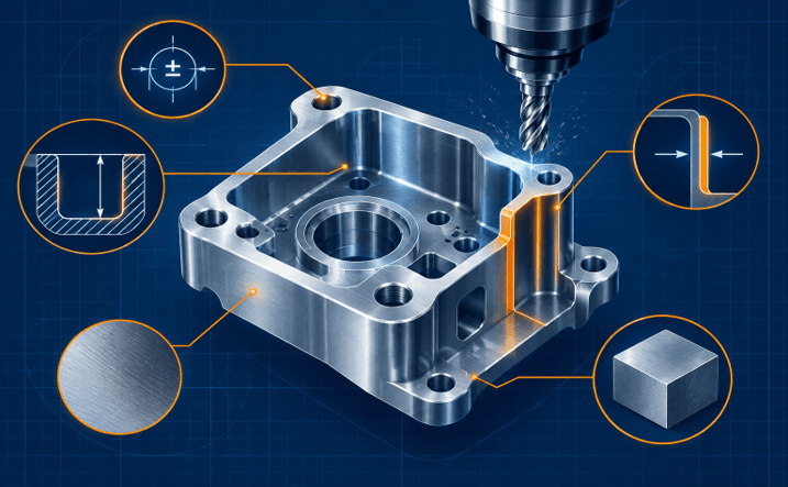
A CNC prototype quote rarely goes over budget because of the machine shop. It goes over budget because of decisions made in the CAD file weeks before anyone requests a quote. Tolerances, pocket geometry, wall thickness, surface finish, and material choice each add cost quietly, and none of them show up as a single line item on the invoice. Product teams familiar with these five decisions can reduce prototype costs and times without compromising on part performance.
1. Why Prototype Budgets Fail Before Machining Starts
Most cost overruns trace back to the design stage, not the shop floor. Production-level precision is frequently carried over to the prototype where only fit and function are required. Then the machinist must reduce cycle times, introduce setups, or procure special tooling that the part doesn’t require in order to meet the specifications. The fix begins with a simple question for each dimension: Does this feature impact the part fit, seal, or motion? If not, it should have a standard tolerance and finish.
Reviewing your CAD model against known cost drivers before you request a quote is one of the most effective cost-saving CNC milling design practices available to a product team, and it costs nothing beyond design time.
2. Over-Tolerancing: When Precision Adds Cost but Not Performance
The tighter the tolerance, the slower the feed rate, the more finishing passes, and the more CMM inspection in a shop. Not only does each tightened tolerance reduce the number of acceptable parts, but each tolerance also reduces the number of usable bar stock or plate, as bar stock or plate has its own tolerance. A design that calls out ± 0.02 mm on a feature that only needs ± 0.1 mm pays for precision the part will never use.
The table below illustrates the relationship between machining and inspection cost as tolerance decreases. When you have some prototypes to choose from, use it as an approximation to make the decision on which features require a tight band.
| Tolerance Band | Typical Use Case | Relative Machining Cost | Inspection Burden |
| ± 0.1 mm | Non-mating housings, brackets, covers | Baseline | Low |
| ± 0.05 mm | Mating bores, press fits, shafts | 1.3x to 1.6x | Moderate |
| ± 0.02 mm | Precision alignment features, seals | 2x to 3x | High, CMM required |
| ± 0.005 mm | Metrology fixtures, optical mounts | 4x or more | Very high, full FAI report |
A practical rule
Use the closer tolerances for the two or three features that determine the fit or alignment. Because all other dimensions are going to use a standard machining tolerance, set this to default and then record the default value in the drawing header, rather than repeating the value on every callout.
3. Deep Pockets, Tight Corners, and Tool-Access Constraints
If the pocket is deeper than roughly 4× the diameter of the tool, the tool will start to run out of rigidity. It deflects, the tool creates chatter, the shop slows down the feed rate, cuts thickness, and sometimes uses a specialty tool with a long, thin neck. Sharp internal corners are a similar issue because a regular end mill cannot make a good right-angle cut, and a smaller corner radius may result in a smaller, weaker end mill.
Most of this expense is eliminated by two design habits. First, try to keep pockets as shallow and narrow as possible for the part. Second, indicate the maximum internal corner radius that can be accommodated, preferably at the same tool diameter set point that is used in the other design steps, but not necessarily.
4. Thin Walls, Fixturing Risk, and Multiple Setups
Thin walls are susceptible to bending or buckling from cutting force and clamping pressure, resulting in chatter, dimensional drift, and, in some cases, scrap parts. In a CAD model, a wall may appear sound, but when you apply clamping load with a vise or fixture, the wall bows measurably. Thin walls also often require additional, slower shop operations to safely retain the part.
This is multiplied by several setups. Each time a part is flipped or re-clamped, the shop starts over with a new datum; and each time the new datum is set, there is a loss of dimensional accuracy and a loss of labor time. Sometimes, a design which combines like features in a single or two setup rather than four or five, is often more cost-saving than any individual tolerance change.
5. Surface-Finish Requirements That Should Be Limited to Functional Areas
Machining a fine surface finish adds real time to the job as it takes more passes to finish, often an extra operation, and closer examination. A lot of drawings call out a finish on the entire part, but only the sealing face, a bearing bore, or cosmetic surface requires a finish.
Use fine callouts sparingly on surfaces where the part’s appearance or behavior is affected, in visible areas, and otherwise keep the part at a standard mill finish. This one change can frequently eliminate an entire secondary operation from the process plan.
6. Material Availability and the Cost of Late-Stage Substitutions
Even if the design is perfect and the material grade, alloy, or stock size required is specified, the design may be out of budget if it is not readily available. If a callout cannot be found in the shop, then the project is delayed until the stock is ordered; if a callout is required within a few weeks, the team may opt for a cheaper, less machinable, less hard, or less readily available product, but this will cause the project to stall.
Be sure of material availability before design is complete, NOT after the RFQ is sent. If it is acceptable, specify a backup grade at the same time on the drawing. If the primary material is backordered, you can proceed directly to the shop without going through the design review cycle.
7. A Pre-RFQ DFM Checklist for Product Teams
The majority of the cost drivers above are identified in a few minutes before the drawing is sent for quote, instead of when the parts arrive. The following checklist highlights areas that are commonly found to be different between an on-budget prototype run and a run that needs reworking.
| Design Area | Check Before You Send the RFQ |
| Tolerances | Apply tight tolerances only to features that mate, seal, or align. Leave everything else at a standard commercial band. |
| Pockets and corners | Keep pocket depth under four times the tool diameter where possible. Use the largest corner radius the design allows. |
| Walls | Keep wall thickness above the minimum your material and part size can hold without distortion. Add ribs instead of thinning a large panel. |
| Setups | Group critical features so the shop can hold them from one datum in one setup. Flag any feature that forces a flip. |
| Surface finish | Call out a fine finish only where the part seals, slides, or is inspected for cosmetics. Leave the rest at a standard mill finish. |
| Material | Confirm stock availability in the exact grade and size before the quote goes out. List one backup grade per part. |
| Drawing notes | Separate critical dimensions from reference dimensions so the shop does not mechanically call out to the tightest tolerance on the page. |
Teams that want a deeper walkthrough of these checks can reference FastPreci’s DFM guide, which covers tolerance selection, tool access, and material review from the machinist’s side of the quote.
None of these 5 decisions will compromise part performance. They need to be directed for precision, geometry, and finish on the parts that need them, and everything else at a standard for easily machined parts. That’s the discipline that makes a CNC prototype from the initial quote to the end part.
Popular on OTW Right Now!




About The Author

Gagan Bhangu
Founder of otechworld.com and managing editor. He is a tech geek, web-developer, and blogger. He holds a master's degree in computer applications and making money online since 2015.