
Ebike Cuts Out Under Load? BMS Amps, Voltage Sag and Connector Faults Explained
Ebike Cuts Out Under Load? BMS Amps, Voltage Sag and Connector Faults Explained
The bike runs perfectly on the stand, pulls away cleanly on the flat, then dies halfway up the first real hill. The display goes dark, or it stays lit and the motor simply stops, and after a minute — or after switching the battery off and on — everything works again. Until the next hill.
This is the single most common fault on a conversion kit, and it is almost never the motor. It is the system hitting a limit: a battery protection trip, voltage sag, a resistive connector, a controller asking for more current than the pack can give, or heat. This guide starts with the one observation that splits the causes in half, then walks a six-step ladder from free checks to the point where you should stop and call someone. It also gives the voltage and current numbers for common packs so you can compare what you see against what is normal.
The Display Test: the first thing to notice splits the fault in half
Before touching anything, answer one question: when the cut-out happens, does the display go dark, or does it stay on while the motor stops?
| What you see | What it usually means | Where to look first |
| Display goes dark; comes back only after the battery is switched off and on | The battery management system (BMS) cut the supply — over-current, under-voltage or temperature protection | Battery state of charge, BMS rating versus controller demand, main power connector |
| Display stays on; motor stops producing torque | The controller stopped driving the motor — brake input held on, Hall or phase fault, controller current or temperature protection | Brake sensors, motor connectors, controller settings and temperature |
| Cut-out only near empty | Low-voltage cut-off reached under load even though resting voltage looked fine | Voltage sag and pack condition |
| Cut-out only on hills, hard starts or with a heavy rider | Current demand exceeds what the pack or a connector can deliver | BMS continuous rating, connector resistance |
| Works cold, fails after several minutes | Thermal protection in controller or motor | Controller airflow, current setting |
| Breaks up over bumps or when the handlebar turns | A loose connector or chafed cable | Every plug in the loom, in that order |
Most riders skip this and start pulling connectors. Do the Display Test on the next ride; it saves half the diagnosis.
Step 1 — State of charge and resting voltage
Charge the pack fully with its own charger and read the voltage with the bike switched on but not moving. Compare it with the table. A pack that reads near the bottom of its range at rest has almost no margin for sag under load and will trip the low-voltage cut-off on the first climb.
| Nominal system | Full charge | Typical low-voltage cut-off region | Healthy rest after a normal ride |
| 36V | 42.0V | around 30–31V | 38–40V |
| 48V | 54.6V | around 40–42V | 50–52V |
| 52V | 58.8V | around 43–45V | 54–56V |
| 60V | 71.4V | around 50–52V | 66–68V |
| 72V | 84.0V | around 60–63V | 78–81V |
A five-bar indicator is not a measuring instrument. If your display shows voltage, note it before the ride and the instant the fault happens.
Step 2 — Understand voltage sag
Every battery’s voltage drops under load, and it recovers when the load is removed. How far it drops depends on the current being drawn, the cell resistance, the temperature, the state of charge and the wiring between pack and controller. Healthy sag on a 52V pack pulling 40A might be 2–4V; a tired pack, a cold pack or a corroded connector can double that, and suddenly a 48V reading at rest becomes 43V under load — and the controller cuts out at its low-voltage threshold.
Lowering the controller’s current limit reduces the symptom. It is a useful diagnostic move and a poor permanent fix if the cause is a damaged pack or a hot connection.
The sag arithmetic, with real numbers
A worked case makes the cut-off visible. A 52V Entry pack rested at 49.5V — about 40% charge, nothing alarming. On a 12% climb the controller asked for 40A. With a healthy pack at that charge level, internal resistance and the XT60 lead might drop the voltage by 3V to 46.5V: fine. This pack, two winters old, sagged 6.5V to 43V and crossed the controller’s low-voltage threshold. The display went dark. At rest, thirty seconds later, it read 49V again and the rider blamed the controller.
The same pack, charged to 56V before leaving, would have sagged to about 49.5V under the same load and carried on — which is why the fault “only happens near empty”. The cure is either a healthier pack, a lower current ceiling, or simply starting the hills with more charge on board. The arithmetic tells you which.
Step 3 — Compare BMS current with controller demand
Motor watts do not tell you battery amps. The controller decides how much battery-side current it may request, and peaks run higher than a simple watts-divided-by-volts sum suggests. The BMS needs a continuous discharge rating above the controller’s configured demand, with margin.
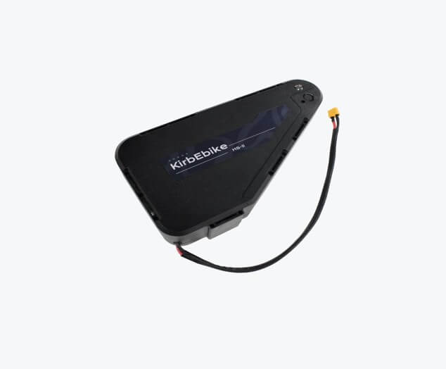
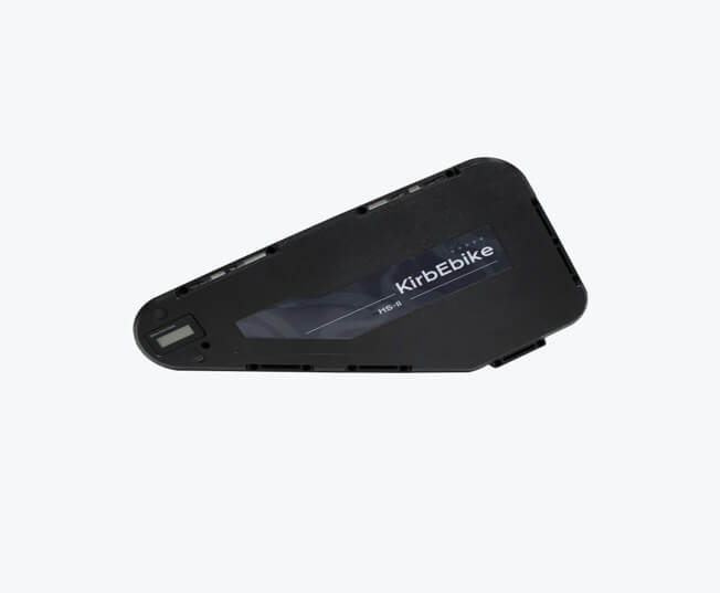
This is where most high-power cut-outs live. KirbEbike’s Taishan and HS-II triangle packs are rated 60A continuous and feed a 2000W controller comfortably. The Entry down-tube packs are rated 30A or 40A depending on model; fit one to a high-current controller left at its default ceiling and the BMS will do its job on the first steep climb — which looks exactly like the first row of the Display Test table. The matched ebike battery options on the battery collection page publish voltage, capacity, BMS current and connector type by model precisely so this comparison can be made before ordering rather than after the first cut-out.
Step 4 — Inspect the high-current connectors
A resistive connection wastes energy as heat and creates an extra voltage drop right at the controller’s input. The bike runs gently and dies under acceleration because current magnifies the loss. XT60 connectors are standard on 36V–52V packs and XT90 on 60V and 72V packs; both are rated for the job when clean and fully mated, and both fail when they are not.
- Darkened or softened plastic around the pins.
- Looseness, corrosion, bent contacts or melted insulation.
- Plugs that can be pulled apart by steering or suspension movement.
- Warmth after a ride — check only with the system powered down.
- Strained crimps or exposed conductor at the cable entry.
Do not bridge, wedge or tape a damaged high-current contact. Replace it.
Step 5 — Controller and motor temperature
Controllers reduce or stop output when they reach a temperature or current limit. A fully potted aluminium controller moves heat to its case better than an open board, but it still needs airflow and it still has an electrical ceiling. A controller in a bag, against a tyre, or in still air behind a battery will protect itself on a warm day and a long climb.
An app-programmable controller helps here because it exposes voltage, current and fault codes while you ride. Save the original profile before changing anything. If heating is rapid at a modest current setting, the fault is mechanical or electrical — inspect the motor connectors and the motor’s own temperature — rather than something a more aggressive tune will fix. The Bluetooth-programmable controller fitted to KirbEbike’s 2000W–3000W kits shows live voltage and fault information in the app, which turns a guess into a reading.
Step 6 — Separate wiring faults from battery faults
If the display stayed on during the fault, the battery probably did its job. Look at the brake cut-off sensors (a sensor held on by a shifted magnet disables the motor without touching the display), the phase and Hall connectors, and the motor cable where it exits the axle.
If the whole system reset and the battery needed a power cycle, look at the BMS trip, pack voltage, the main battery connector and the power wiring first. The Display Test already pointed you here; Step 6 is confirming it.
The safe repeatable test
Once you have a suspect, reproduce the fault under control.
- Record battery voltage, state of charge, controller settings and the ambient temperature.
- Inspect every connector and the wheel’s axle retention before applying load.
- Test at low current in a traffic-free area.
- Increase load gradually while watching voltage and any fault indication.
- Stop immediately if a connector, the battery or the controller becomes unusually hot, smells abnormal or shows damage.
- Change one variable, then repeat. Never bypass the BMS to “see if that’s it”.
- Leave pack opening, high-current measurements and internal repair to a qualified technician.
What never to do
- Bypass or swap the BMS for an unknown higher-current unit.
- Fit a larger fuse or bridge a protection device.
- Repeat full-throttle cut-outs to “test” the battery.
- Mix chargers because the plug fits.
- Assume motor wattage equals the controller’s battery-current limit.
- Keep using a connector that is hot, loose or discoloured.
A cut-out is data
Treat protection as a boundary, not an obstacle. Every cut-out carries information: state of charge, gradient, current setting, temperature and whether the display reset. Write those five things down when it happens and the cause is usually obvious within two rides. A correctly matched battery, controller and loom should deliver the requested load without ever reaching a BMS trip; if yours reaches one regularly, one of the three is wrong, and raising a limit is the one change guaranteed to make it worse.
Frequently asked questions
Why does my ebike cut out only when accelerating?
Acceleration is when current demand peaks. That exposes voltage sag, a BMS continuous rating below the controller’s demand, a resistive connector or controller protection. Do the Display Test to see which.
Can lowering the DC current setting stop the cut-outs?
It reduces demand and is a useful diagnostic step. It does not repair damaged cells, a loose XT60 or an undersized BMS. Find the cause before relying on the setting.
Why does the battery work again after switching it off and on?
The BMS entered protection and reset when power was cycled. The reset is normal; the trip is the information. Confirm what triggered it rather than resetting it repeatedly.
Should I bypass the BMS to get more current?
No. The BMS provides over-current, under-voltage and temperature protection for lithium cells. If you need more current, you need a pack rated for it — a 60A pack for a high-current controller — not a pack with its protection removed.
How much voltage sag is normal?
A few volts on a healthy pack under hard load, recovering immediately when the load is removed. Sag that takes a 52V pack from 54V at rest to the mid-40s under load points to a tired pack, a cold pack or a resistive connection.
Publisher metadata
- SEO title: Ebike Cuts Out Under Load? BMS Amps, Voltage Sag, Connectors
- Meta description: A display test that splits ebike cut-outs in half, a six-step diagnostic ladder, full-charge and cut-off voltages for 36V–72V packs, and why a 30A BMS on a 2000W controller trips on every hill.
- Suggested URL: /ebike-cuts-out-under-load/
- Target publisher: TBD — EV or battery-technology site preferred
- Link 1 (≈50%): “matched ebike battery options” → https://kirbebike.com/collections/ebike-kit-battery
- Link 2 (≈66%): “Bluetooth-programmable controller” → https://kirbebike.com/products/displays-and-controllers
- Image 1: https://cdn.shopify.com/s/files/1/0621/8412/8665/files/Group43.png — alt: Heavy-gauge XT discharge lead carrying current from the battery pack to the controller
- Image 2: https://cdn.shopify.com/s/files/1/0621/8412/8665/files/Group42.png — alt: Sealed ebike battery case seen side-on, with the XT connector and charge socket
Popular on OTW Right Now!



About The Author

Gagan Bhangu
Founder of otechworld.com and managing editor. He is a tech geek, web-developer, and blogger. He holds a master's degree in computer applications and making money online since 2015.